
Integrating a LoRa system with a Teltonika RUT router
 GNS Engineering Team 2 min read

LoRa sensors (water meters, temperature, vibration, level) usually speak LoRaWAN or a private LoRa protocol; Teltonika Networks does not make LoRa radios. In practice, the LoRa network is connected to a Teltonika RUT router, which backhauls the data over 4G/5G to RMS or the customer cloud.
Below are the two common integration options, with a reference wiring diagram.
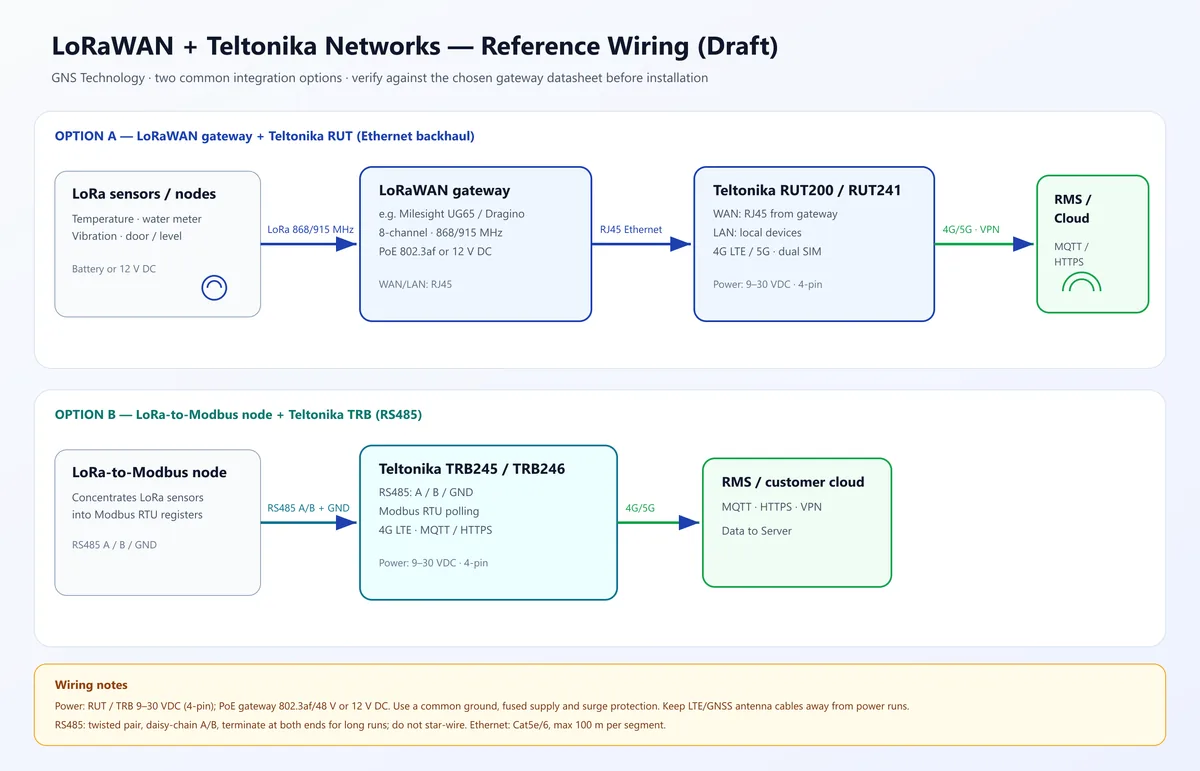
Option A: LoRaWAN gateway + RUT (Ethernet)
- LoRa sensors → LoRaWAN gateway (e.g. Milesight, Dragino, Multitech)
- Gateway LAN → RUT WAN (Cat5e/6, up to 100 m)
- RUT backhauls over 4G/5G via VPN / MQTT / HTTPS to RMS or the customer cloud
Typical fit: water utilities, smart city, environmental monitoring, remote sites.
Option B: LoRa-to-Modbus node + TRB (RS485)
- LoRa sensors → LoRa-to-Modbus node
- Node RS485 A/B/GND → Teltonika TRB245 / TRB246
- TRB polls Modbus registers and sends them over 4G to the cloud
Typical fit: industrial sensors, energy/utilities, PLC integration.
Wiring notes
| Item | Recommendation |
|---|---|
| Ethernet | Cat5e/6, gateway LAN → RUT WAN, up to 100 m |
| RS485 | Shielded twisted pair, do not swap A/B, 120 Ω termination at both ends for long runs |
| Power | RUT/TRB 9–30 VDC; gateway PoE 802.3af or 12 V DC |
| Protection | Separate fuse, surge protection, common ground |
| Antennas | Keep LTE/GNSS antennas away from power runs |
Data flow
Sensors → LoRa gateway / Modbus node → RUT/TRB → 4G/5G → RMS / customer cloud (MQTT, HTTPS, VPN).
How GNS helps
GNS Technology is a Teltonika Networks Value Added Reseller in Hong Kong. We can help with:
- Choosing the LoRa gateway and Teltonika model
- Wiring, power and antenna placement
- Modbus / MQTT / VPN configuration
- Centralised management with RMS
Contact us to discuss your site.